There are a few good reasons to build this amplifier. The biggest one is that it's a very simple circuit (for an amplifier), but sounds good and is pretty useful. As such, it's an excellent project for those looking to learn about audio circuits, or analog circuits, or even circuitry in general.
Secondly, this amplifier is battery-powered and portable. It's designed to be plugged into an MP3 player, so if you find you need to attach external speakers to your MP3 player a lot, this will work. (I use this circuit as the main amp stage on my stereo bike.)
This circuit is based around the TDA-1554Q chip made by NXP electronics. You can buy this part from Digikey for around $2 - $3 at the time of this writing, but they emailed me a couple weeks ago to say that NXP has discontinued the part. So if it isn't available anymore, you can email me and I'll mail you one for $10 (sorry to gouge, but I've only got a few left). Having said that, NXP's other parts in the TDA line that work pretty much the same.
The datasheet (available online) contains a working schematic for a two-speaker setup. It was published in 1991, back when NXP was still Phillips and I was barely an infant. Nonetheless, it is the basis for the circuit that we'll be building.
You will note I have no mute/standby circuitry - you may want to add this in, but I have never had a use for it, since at these low voltages simply cutting power is fine.
The above schematic looks pretty simple, but it's a little trickier than that. Here is a complete part list:
I am using a 12V house-alarm backup battery. While the TDA1554Q will accept a power supply from anywhere between 6 and 18 volts, be aware that some components may need adjusting. (In particular, the 33μF capacitor may be insufficient for ripple rejection when playing loud music with an 18 volt supply.)
The TDA chip dissipates a lot of power - around 4 or 5 amps peak. This means not only that you need a pretty strong power supply (wall jacks won't cut it), but also that you need to heatsink the chip pretty damn well. I solved this problem by bolting it directly to the inside of my project box, using Artic Silver CPU gunk. This works, but keep in mind that the backplane of the TDA chip is a power ground, so you're committing yourself to using the chassis as ground. However, with the gunk in place this is not a clean connection, so don't rely on it as a main ground connection.
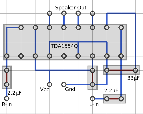
Bolting the back to the chassis introduces another problem: pins 6, 8, 10 and 12, the speaker output pins, are right below the backplane, making them very difficult to access. In the end I used an inch or two of twisted-pair CAT5 wire and snaked them around, but the sound signal is in excess of these tiny wires' ratings. It works, but is poor engineering practice. If you think of a better solution to this, don't hesitate to email me.
Given all this, here is the layout I used when I built this circuit on a prototype board (with minor modifications). I have no pictures of this version of the circuit, unfortunately.
I hope this helps somebody.
At this point, all that is left is to wire in the jacks and switches, and you've got a working, self-contained amplifier. I won't tell you how to do this, but I have a few words of advice:
October 2009
Andrew Poelstra