In this article I will discuss two major changes to the original amplifier I designed for my bike. Firstly, we will move away from the discontinued TDA-1554Q stereo amplifier to a dual-channel design based on the newer TDA-2050 chip. This not only gets us away from the discontinued part number, but also gives us more power (32W vs 22W per channel, plus a power range slanted more towards a 12V supply) and lets us isolate each channel's circuitry as much as we want.
Secondly, we will add a guitar preamplifier to each channel using a simple JFET design using the J201. Because, why not?
If you haven't already, check out the data sheet for the TDA-2050. It has some very useful sample schematics, and includes an explanation of each component and what it is used for. Kudos to the folks at ST Microelectronics for putting this together.
Because the TDA-2050 is a single-channel amp, we can create a much simpler with it than with a stereo amp, and put two or more of them together to add channels. This article assumes you will stick with two, though there's no reason not to add more. Also, this chip has only 5 pins - far easier to route than the 17-pin monstrosity that was the TDA-1554Q! However, there are more external components to add than there were with the TDA-1554Q, so not everything is peaches and roses.
The guitar pre-amp is a basic JFET-based voltage amplifier. If you've taken a FET course before, you'll recognize this circuit. If not, that's fine too. In either case, J. Donald Tillman has an excellent article introducing the concept in a sound-amplifier context. My circuit is a little bit different, but that article was what I based it on.
The final design change I will recommend is this: if you are building a stereo bike, use an XLR connector for sound input. Failing that, use a 3-pin DIN connector. Either one will be stronger and stabler than a regular male-male 3.5mm stereo connector, which will jostle around, break easily, and generally give you trouble. This article does not discuss connections or casings, so I won't mention this again.
There are a lot more parts required for this project! However, it is still not that complicated, and well within the bounds of what a casual hobbyist can do. Here is a complete list of what you will need (per channel):
I am not an electrical engineer. I don't do this sort of thing that often, and I don't have any schematic or PCB software that I use often enough to feel comfortable with. So I drew this picture of the solder side of my protoboard layout:
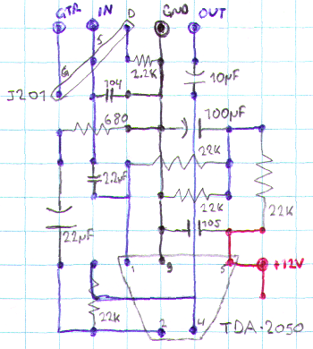
Addendum: In addition, connect a 10k resistor from the bottom-right (+12v line) to the top-left (guitar input), or else the guitar amp will not be biased correctly and will not work.
As for connections, I have a normal DC power jack and 1/4" plug mono guitar input. Sound is output through RCA jacks and input through a 3-pin DIN connector (using a custom cable to plug into the headphone jack of my MP3 player).
Though the TDA-2050 is rated at 35W, I am only powering it using a 12V house-alarm backup battery. This means that the actual power output is probably somewhere in the 10-15W range. Unfortunately, the datasheet for my previous chip the TDA-1554Q, does not have the necessary supply-vs-output graph for me to make a comparison. But this one sounds a lot louder, and that's all I care about.
I'm not going to say "pictures to come" at the end of this article because the truth is, I'm never going to get around to taking pictures of my amplifier. Hopefully, this article will help you to build your own, so you don't have to imagine it. Thanks for reading.
June 2010
Andrew Poelstra